
Custom Furniture Lighting
Custom LED module development for furniture brands, cabinet makers, shopfitters and OEM/ODM product teams.
View detailsFlexible Strip Project Development
As your custom LED strip lights supplier, VST turns the complete run plan, PCB approach, cut points, leads, connectors, controls, protection, and mounting conditions into a manufacturable assembly. Installed samples and a released production reference support consistent segment kits, labeling, appearance, and later supply.
Send your run map, segment quantities, channel dimensions, electrical system, controls, environment, and target market.
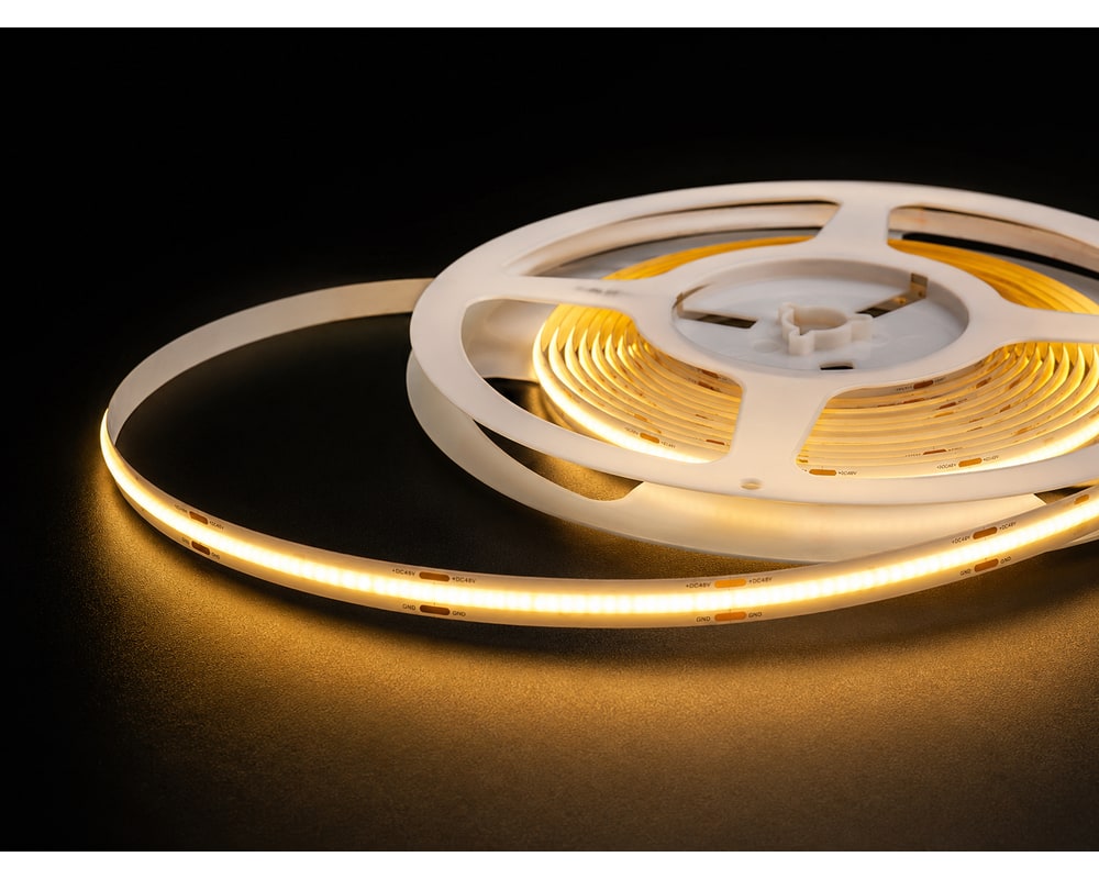
When you brief a custom LED strip lights factory, provide the complete installation rather than only a reel description. Segment lengths, corners, feed points, cut pattern, connectors, channels, mounting surface, ambient conditions, controls, viewing distance, and assembly sequence shape the useful design. VST maps the strip and host product together without assuming voltage, wattage, protection grade, chip brand, adhesive, or reel length that has not been specified for the project.
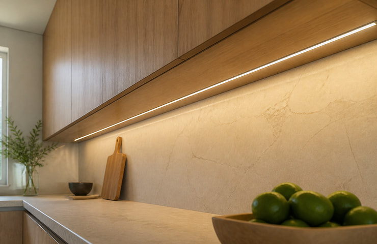


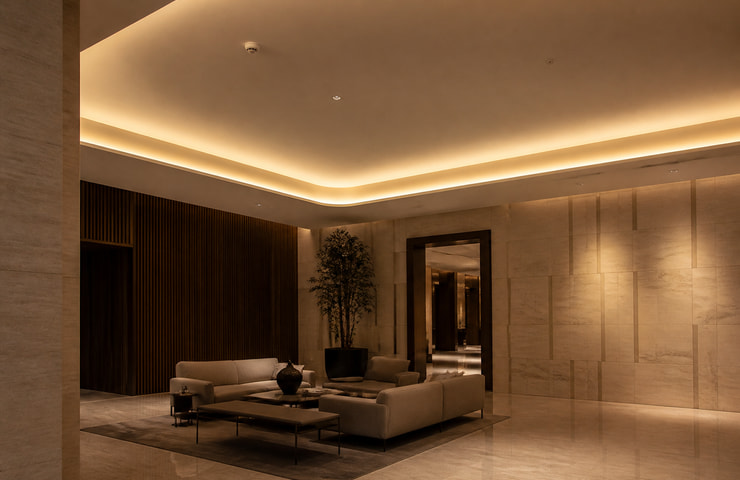
Purchasing risk: Installers may cut and connect inconsistently, causing waste, rework, mismatched leads, or site delays.
Confirm: Run lengths, cut positions, corners, feed points, connector locations, labels, and kit grouping.
VST solution direction: Convert the project layout into a controlled segment, lead, and packaging plan before production.
Purchasing risk: PCB fit, diffuser clearance, adhesion, heat path, and appearance may fail in the final assembly.
Confirm: Channel drawing, internal width, diffuser, mounting material, orientation, ambient conditions, and access.
VST solution direction: Evaluate strip, profile, diffuser, mounting, and thermal path together and test the intended assembly.
Purchasing risk: The released light appearance may require a mechanical redesign when the real interface is added.
Confirm: Connector type, mating part, cable length and approach, polarity, strain relief, and assembly method.
VST solution direction: Include final connection details in the representative sample and released drawing.
Purchasing risk: The treatment may conflict with cut points, connectors, flexibility, dimensions, heat, or the end-product authorization route.
Confirm: Exposure, cleaning, moisture, chemicals, bends, terminations, installation, and required validation.
VST solution direction: Discuss protection as a complete strip-and-termination construction subject to project validation.
A custom LED strip lights supplier should plan the installed assembly, not only the flexible PCB. The scope can include run layout, PCB width, source format, cut pattern, light quality, electrical input, leads, connectors, controls, protection, retention, profile, labels, kits, and packaging. Provide the host-product constraints and priorities so VST can separate a platform adaptation from work requiring a dedicated PCB, tooling resource, or additional validation.
Segment lengths, cut positions, feed points, corner strategy, labels, and kit grouping can be discussed.
Buyer input: Every run length, corner, feed location, tolerance, quantity by segment, and installation sequence.
PCB width, source format, density approach, circuit layout, and visual-line target may be evaluated.
Buyer input: Available width, diffuser distance, viewing conditions, thermal surface, and light-quality priorities.
Input approach, connectors, leads, solder or connection method, dimming, and control architecture can be coordinated.
Buyer input: Electrical source, run plan, control protocol, connector constraints, polarity, and cable requirements.
Coating, sleeve, encapsulation approach, channel, diffuser, adhesive, clips, and end treatment may be discussed.
Buyer input: Moisture, dust, cleaning, chemicals, bends, temperatures, mounting surface, and validation needs.
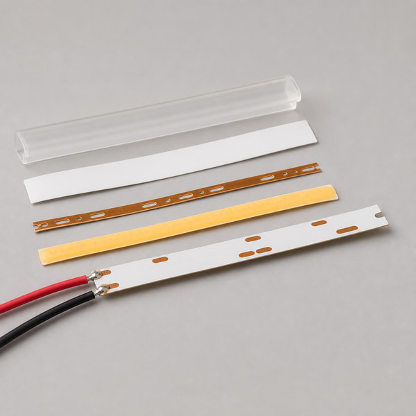
Select a strip format from the viewing condition, channel and diffuser, control requirement, electrical architecture, exposure, thermal surface, run map, connection plan, and cost target. COB and SMD directions produce different appearance and assembly trade-offs; tunable or color-control formats add channels and system complexity. Treat protective construction and terminations as a separate choice, then evaluate the complete sample inside its intended profile.
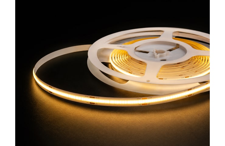
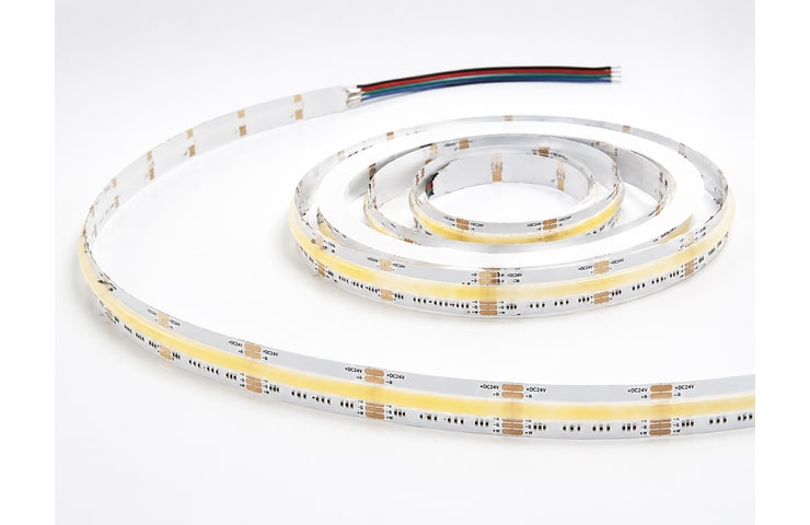
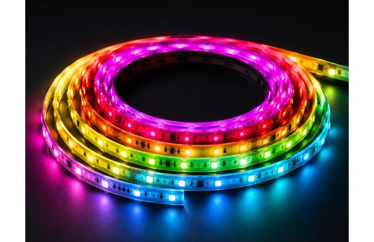
| Decision factor | Continuous-Light | Conventional SMD | Color-Control | Buyer guidance |
|---|---|---|---|---|
| Visual source pattern | Designed for a smoother continuous appearance at close viewing. | Source points depend on density, diffuser, and viewing distance. | Appearance varies with channel count, source layout, and diffuser. | Evaluate the installed sample at the real viewing distance. |
| Control complexity | Usually selected for a defined single or limited light function. | Can support several standard control directions, subject to design. | Requires coordinated multichannel control, wiring, and software logic. | Start from the host system and controller architecture. |
| Profile and connector fit | Verify PCB width, cut plan, terminations, and repair approach. | Many interface directions exist, but profile clearance still governs. | Additional conductors and connectors consume more space. | Provide the channel and connector envelope before sampling. |
| Thermal and electrical planning | Continuous construction and run load require suitable mounting evaluate. | Depends on source density, circuit, run, and mounting surface. | Multiple channels can increase load and control-system complexity. | Evaluate the complete run and worst operating mode. |
Run lengths, PCB width, bend orientation, source format, cut pattern, voltage and feed layout, leads, connectors, controls, protective treatment, thermal surface, profile, labels, and kit grouping must work as one system. VST, a custom LED strip lights manufacturer, begins with your run map and host-product section, then separates shared platform elements from unique segments. Engineering can define circuit and connection directions, map feeds and cable exits, prototype representative lengths, assemble them with the intended profile or mounting surface, and measure or inspect the agreed optical, electrical, thermal, and fit criteria. Feedback leads to documented adjustments in PCB, source spacing, terminations, protection, retention, or pack organization. Once the sample set meets the project criteria, VST releases segment drawings, connection and labeling rules, workmanship references, and inspection points. Repeat orders use those controlled records, agreed materials, process checks, and change tracking so multiple lengths remain identifiable and consistent.
Custom LED strip lights should be evaluated with the released PCB, source layout, segment length, electrical feed, control mode, profile, diffuser, connectors, and protective treatment. VST supports integrating-sphere, aging, visual, assembly-process, and thermal checks where appropriate. Agree the methods, durations, limits, documents, and certification route for the released design and destination market; equipment images alone do not establish a pass result.
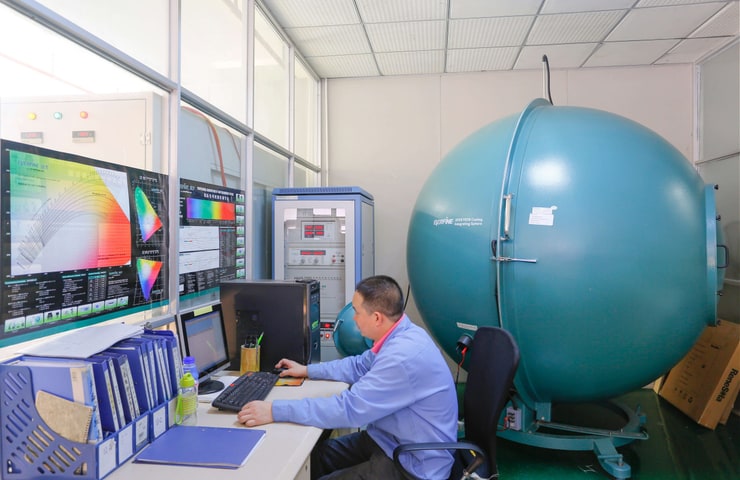
Purpose: Evaluate agreed optical, color, and electrical targets on the evaluated strip configuration.
Method: Measure relevant sample performance with integrating-sphere equipment under agreed project conditions.
Acceptance criteria: Optical and electrical readings meet the limits set for the released strip sample.
Evidence: Measured optical and electrical data for the released strip configuration when reporting is included.
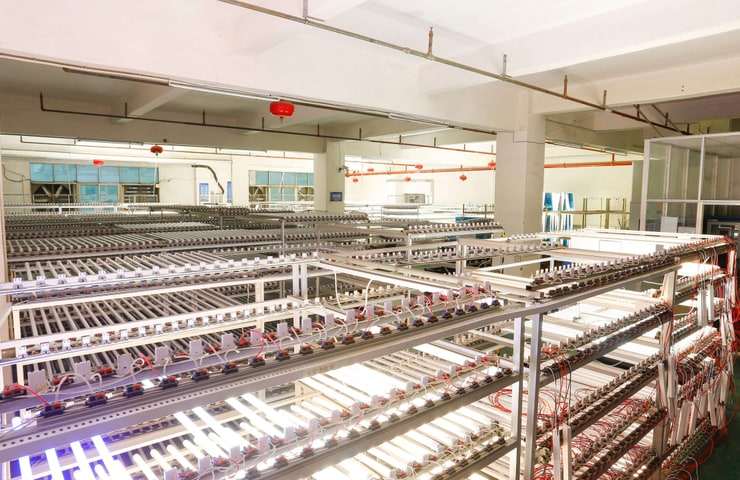
Purpose: Help identify early instability, visible change, connection concerns, or assembly variation before release.
Method: Run representative units under the project-defined operating and observation schedule.
Acceptance criteria: No unacceptable instability, visual shift, or connection issue appears during the agreed operating evaluate.
Evidence: An operating-check record tied to representative units when the documentation scope calls for it.
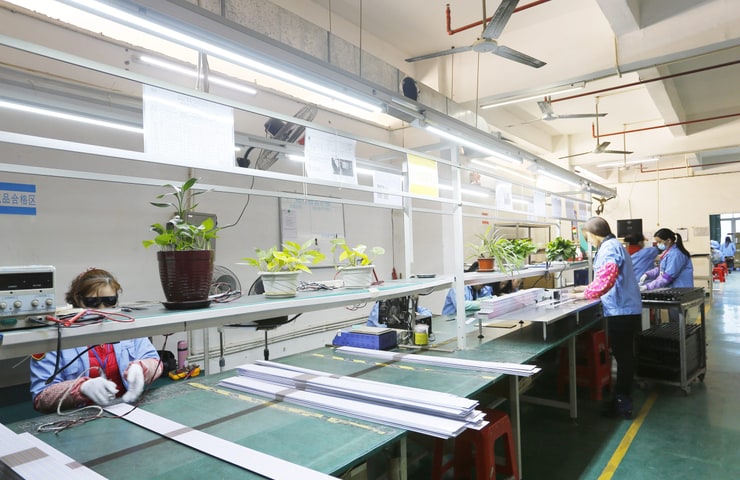
Purpose: Control PCB appearance, source placement, soldering, connectors, leads, labels, segment lengths, and workmanship.
Method: Inspect against the released drawing, sample, workmanship criteria, and packaging requirements.
Acceptance criteria: Segment length, soldering, leads, labels, and workmanship match the accepted reference.
Evidence: Production-inspection results for segment identity and workmanship when these records are part of the order.
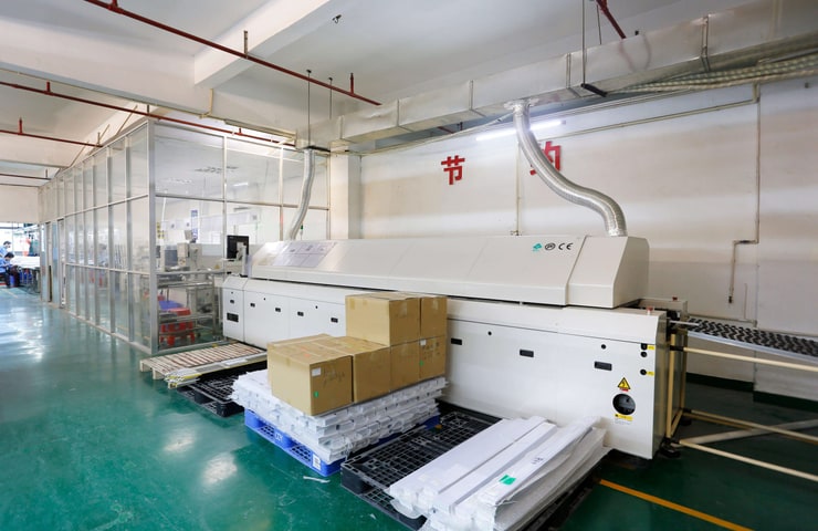
Purpose: Reduce risks from connection, assembly, and process variation in repeat production.
Method: Evaluate relevant process settings and workmanship at a general project and production-control level.
Acceptance criteria: Process settings and connection quality remain within the released production controls.
Evidence: Process-check information for connection quality when a documented production record is specified.
| Market | Standard / requirement | Scope | Confirmation note |
|---|---|---|---|
| EU projects | Relevant electrical, EMC, material, component, system, and end-product requirements | Depends on the strip, driver, controller, installation, finished product, and applicable EU route. | Verify EU documents and any system-level acceptance needs for the released strip assembly. |
| North American projects | Relevant component, electrical, installation, system, and end-product requirements | The required evaluation route depends on the released strip assembly and final product. | Establish the North American component, installation, or end-product route before order release. |
Verify PCB, source, electrical, color, segment, connector, protection, and revision data required.
Verify segment lengths, feed points, connectors, leads, labels, polarity, controls, and kit grouping.
Verify channel, diffuser, mounting surface, thermal path, cable route, and assembly sequence.
For each strip model, typical starting quantities are 500 units with light customization and 1,000 units with high customization. Platform-based adjustments to segmenting, leads, labels, or packing generally follow the lighter route; a dedicated PCB, major electrical or optical change, tooling, protection process, or special production method can place the work in the deeper route. As a custom LED strip lights vendor, VST records the final MOQ for the selected configuration in the quotation.
VST can produce development samples for custom strip assemblies. Processing charges cover project-specific setup, material preparation, cutting, soldering, assembly, programming or control coordination where relevant, and evaluation. Dedicated PCBs, fixtures, molds, profiles, or other new resources may involve separate tooling costs. Some qualifying sample expenditure can later be returned or applied toward a production order. The eligible spend, applicable order, and credit treatment are discussed for the individual program and stated in its quotation or order terms.
Normal planning windows are 15–25 working days for a light-custom sample, while volume production is normally scheduled within 20–30 working days. A high-custom strip program generally uses 30–50 working days for sampling; its production lot normally occupies 25–35 working days. Counting starts only after the full technical brief, relevant sampling cost, any NRE or tooling payment, deposit, and specified order prerequisites are complete. With stable demand, VST can reserve agreed LEDs, PCBs, connectors, protection materials, or packing components to accelerate later scheduling without creating a fixed delivery guarantee.
Tooling or NRE can arise from a dedicated PCB, mold, extrusion, cutting or soldering fixture, test fixture, optical component, connector solution, protective-process resource, or another item created only for the strip program. A qualifying mold or tooling amount may be credited toward a later production invoice; it is not automatically refundable. The quotation identifies the eligible amount, the order that activates the credit, and the settlement method for the specific program.
Continuity for segmented strip programs depends on controlled materials, circuit and connection records, accepted appearance references, process settings, labeling rules, and change communication. VST coordinates established supply sources and staged production checks around those controls. When demand stays stable, forecasts can support advance preparation or holding of agreed critical inputs, improving availability and repeat-batch scheduling. Reserved materials are not guaranteed finished-goods stock; actual segment mix, revision, release quantity, and current component status still determine each production schedule.
Custom strip packaging can include reels, cut-length trays or bags, segment kits, identification labels, barcodes, shipping-carton marks, brand presentation artwork, operating instructions, user manuals, and other protective packs within the final order scope. VST organizes each pack around segment code, lead or connector orientation, kit grouping, and installation sequence while protecting solder joints, optical surfaces, and accessories during handling. Shipment support follows the released plan; freight terms, carton data, destination costs, and transit windows are supplied only for the actual dispatch arrangement.
Continue by comparing COB and SMD source formats, rigid linear modules, channels and diffusers, connectors, drivers, dimming or color-control paths, and installation or thermal guidance. These adjacent solution areas help determine whether a flexible strip, rigid assembly, or complete kit best matches the viewing condition, service route, electrical architecture, and host-product geometry.
Custom LED module development for furniture brands, cabinet makers, shopfitters and OEM/ODM product teams.
View detailsOEM / ODM LED Module Development · Shenzhen, China Custom LED Lighting & Module Development for Global B2B Buyers We develop LED modules, light…
View details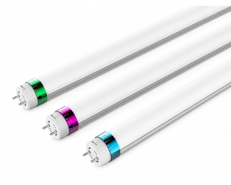
Develop a custom tube light around the mechanical, optical, and electrical limits of equipment, display furniture, refrigerated cases, or specialist products. As a custom…
View details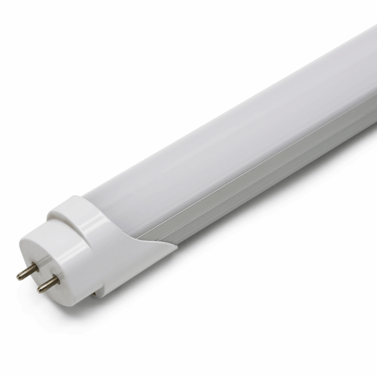
1200mm 18W T8 LED tube light for mainstream office, school, supermarket, workshop, and commercial replacement projects. It offers 150lm/W efficiency, >0.92 power factor, 160°…
View details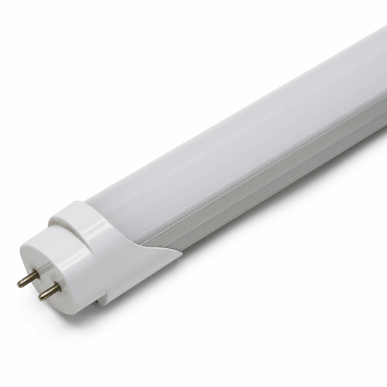
1500mm 22W T8 LED tube for warehouse, workshop, supermarket, garage, and industrial replacement projects. With 150lm/W efficiency, 50,000hrs lifespan target, 160° beam angle, and…
View details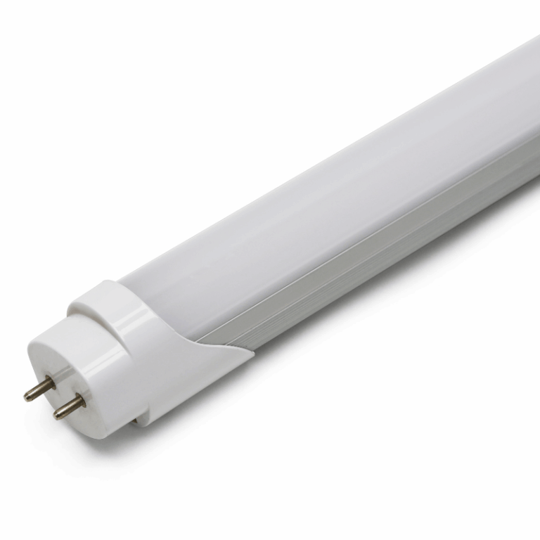
2400mm 36W T8 LED tube light for long-run warehouse aisles, production lines, logistics areas, and large commercial replacements. It provides 150lm/W efficiency, AC85V-265V input,…
View detailsWhat can be customized on custom LED strip lightsWhat can be customized on custom LED strip lightsWhat can be customized on custom LED strip lightsWhat can be customized on custom LED strip lightsWhat can be customized on custom LED strip lightsWhat can be customized on custom LED strip lightsWhat can be customized on custom LED strip lightsWhat can be customized on custom LED strip lightsWhat can be customized on custom LED strip lightsWhat can be customized on custom LED strip lightsWhat can be customized on custom LED strip lightsWhat can be customized on custom LED strip lightsWhat can be customized on custom LED strip lights
Depending on feasibility, discussion may cover PCB width and circuit approach, source format and density, light-quality targets, cut pattern, factory-cut segments, connectors, leads, controls, protective treatment, labels, reels, kits, and packaging. The useful options depend on the profile, mounting surface, run schedule, electrical system, environment, quantity, and validation. Provide these inputs before selecting individual features.
Send an installation drawing that marks each cut segment, turn, electrical feed, lead exit, mating connector, channel, mounting surface, and assembly sequence. Add quantities by segment, dimensional tolerances, label codes, kit groups, power supplies, controls, and destination market. Identify which runs share a platform and which are unique. VST can then plan cutting, wiring, voltage-drop analysis, assembly, packaging, and repeat-order control around the actual installation.
Start with viewing distance, diffuser, desired visual line, channel size, heat path, run length, connection needs, controls, quantity, and cost priority. A continuous-light COB approach can reduce visible source points, while conventional SMD formats provide broad configuration flexibility. Neither is universally better. Compare installed samples using the real profile and diffuser, then accept the format that meets the host-product priorities.
They can be discussed as project-dependent targets. PCB width must fit the channel and component layout while supporting electrical and thermal needs. Cut length follows the circuit design and affects segment planning, waste, connectors, and service. Supply the internal profile width, bend orientation, required segment lengths, tolerances, and quantity. Dedicated PCB work, tooling, or MOQ may apply.
Define the mating interface, conductor count, polarity, cable type, length and exit approach, connector envelope, strain relief, assembly sequence, and whether the connection must pass through a profile or opening. For multiple segments, provide a coding and kit plan. The final lead and connector should be included in the representative sample because they affect fit, reliability, service, packaging, and production inspection.
Dimming, tunable, multichannel, or dynamic-color directions can be evaluated when the controller, power architecture, wiring, communication method, operating modes, and host-product requirements are clear. Additional channels affect PCB layout, connectors, cable space, power, heat, software coordination, and validation. Provide the controller or protocol information and define the expected behavior so the strip and system interfaces can be evaluated together.
Describe the actual exposure to moisture, dust, cleaning, chemicals, temperature, bends, mechanical handling, and installation method. Coating, sleeve, or encapsulation directions affect dimensions, flexibility, light output, heat, cut handling, connectors, and terminations. A requested IP grade alone is not enough. VST discusses a suitable construction and validation scope, while final protection and certification must be verified for the released assembly.